FLIP Platform
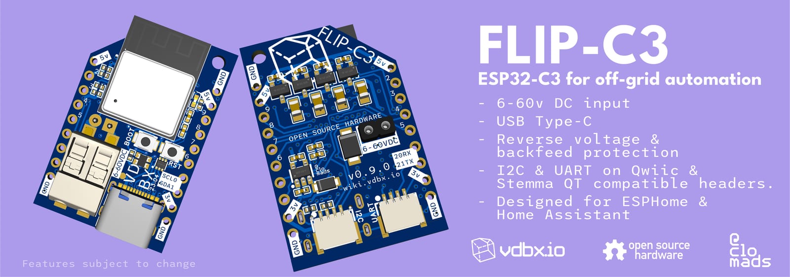 Marketing render of the FLIP-C3 as first prototype boards are ordered. 23.04.04
Design Philosophy
Section titled “Design Philosophy”The FLIP platform is a set of standards between circuit designs with the intention of easy install within 12-48v lithium battery systems. It designed as a modular system to create IOT hardware for modern open-source automation systems. The platform will consist of mainboards which have processing and network capabilities and the modules which will provide or interface with switches, lighting, sensors, relays, dimmers, etc.
The mainboards should be able to power themselves and basic modules from the an on-board buck regulator. Additional power modules can be placed in parallel with the base moule built into the mainboard.
I2C should be considered a high-priority interconnect due to its capability for easy expansion and daisy-chaining. In as many situations as possible, modules should be able to function as either tethered I2C device or with a FLIP mainboard installed. A standalone device (mainboard with module) should be able to connect to it’s mainboardless version of itself via the Qwiic & Stemma QT compatible connector. In some cases, smaller boards could stack infinitely, limited only by the available I2C addresses. We’ve currently coined these smaller boards as backpacks.
- Power modules should be tolerant to 60v DC input which covers up to 16s Lifepo4 systems.
- 5v with at least 1A of available power without extra cooling
- Future should offer higher voltage ranges for electric
- 60v board to board header for distribution
- USB-C with 5v buck converter
- Standardized 2.54mm dual header layout between boards
- Passthrough stacking pin/socket headers included
- Stemma QT & Qwiic compatible SH 1.0 connectors
- I2C & UART
- Home Assistant as target platform
- ESP32 for Wifi and Ethernet
- ESPHome Firmware
- ESP32 for Wifi and Ethernet
- Future Targets
- RP2040
- EBYTE Modules for Zigbee
- PTVO Firmware?
- Thread/Matter
- Must have simple device provision like ESPHome
Software
Section titled “Software”You will always be able to write whatever code want to a FLIP device, but our priority is ESPHome due to its ease of use with beginners. Technically minded artists, home automation enthusiasts, and other makers who struggle with will likely find it easier, especially if they have experience with somthing like HTML/CSS.
ESPHome is backed by the Open Home Foundation started by Home Assistant/Nabu Casa.
WLED is a high priority platform, but we will likely work within the bounds of existing functionality. Its development is progressing steadily and there is extreme interest in WLED specific features in hardware.
TASMOTA is very popular, and we look forward to seeing any work you do with it. At the moment, we are not going to be focusing any efforts on this platform.
Possible or Realized Products based on FLIP
Section titled “Possible or Realized Products based on FLIP”- Switch Panel (Unnamed)
- PwrTool Family
- Large main system shunt
- Small Handheld coulometer with XT60, PP45, screw-in, etc. connection options
- Branch Manager - Smart power distribution panel
- 8x High power p-channel mosfets
- Lighting Director - PWM Mosfet controller for DC lighting devices.
- Backpacks - should be the same size as the FLIP itself.
- PWM mosfet 4x via direct connection to GPIO
- RS485 to TTL for Solar Chargers
- 3A+ Switching power supply
- 16020 has a 16030 pin compatible 3A version but will require external component selection. Good for LED control board?
- RGB Addressable LED control (with DC buck?)
Switching Buck Regulators
Section titled “Switching Buck Regulators”Summary
Section titled “Summary”Attempt to find a balance of price and size for a small 1-3A buck converter capable of up to 60V input. This came about when looking at postage stamp or smaller buck converters on AliExpress where input voltage is all over the place and not a headline feature apparently. I would like to have a standardized power supply that can work within most common battery systems without having to sort through 100s of pages of AliExpress to find the one you need.
The best one I’ve found on AliExpress is based on the MP4560DN which handles up to 60v and provides 2A continuous. LCSC does not list it and it is and extended part for JLCPCB. It is also short of my requirements.
Research
Section titled “Research”Before attempting the LDO experiment, I had done several hours of research on DC switching regulators within the 60v req and landed on creating 3 schematics based on the datasheet suggestions for the following ICs:
- LMR16020
- as low as $0.55 at 100 qty
- components are compact
- seems to fit in LDO footprint of FLIP-C3
- LMR36015
- smallest footprint
- $5 each until 200 units then $2 ea
- no diode necessary
- TX4414
- $0.24 @ 5u / $0.17 @ 150u
- Large external components per datasheet
- will need engineering to reduce size.
History
Section titled “History”Research started by looking at the cheapest chips on LCSC and making schematics from what the datasheet suggested. Tho I seem to have a very expensive IC in my list and I don’t remember why.
I have also scoured TI’s website while comparing it to LCSC’s list, but I was moving on to the LDO experiment at this point. When I came back I already had 3 schematics and board layouts to pick from.
Future
Section titled “Future”Even if we chose an IC suitable to launch the FLIP-C3 and the products it lives in, I intend to continue researching ICs to improve future revisions and maybe create a “Booster Pack” in case certain stackups of PCBs might need more power. A 3-5A converter with an output for addressable LEDs might be a great idea. We could also have a switch to swap between 5v and 12v
I’m hoping documentation improves as we test individual buck ICs.
LMR16020 - Active Choice
Section titled “LMR16020 - Active Choice”- 4.3 V to 60 V Input Range
- 2A Continuous Output Current
- Alternate 3A version - LMR16030
- Ultra-low 40 µA Operating Quiescent Current
Datasheet
Section titled “Datasheet”https://www.ti.com/lit/ds/symlink/lmr16020.pdf?ts=1682401856589
23.04 - First Batch Testing
Section titled “23.04 - First Batch Testing”Hindsight - 23.08
Section titled “Hindsight - 23.08”For those in the same situation I was before starting this project, a linear regulator keeps current the same on the input and output so any excess power is disipated as heat. This makes them unsuitable for large voltage drops at anything more than a few milliamps. Below are notes of my experience of utter failure thinking an LDO would work for this application.
Summary
Section titled “Summary”For the initial design of the FLIP-C3, an LDO from Seward Electronics was chosen due to its max suggested input voltage of 60v. The SE8650X2-HF has a current limit of 200ma so it was determined that four(4) of them be used in parallel considering the potential needs of the ESP32-C3, a WS2812B LED, a red LED plus some overhead.
The initial design duplicates the suggested circuitry for each LDO, so each input has a 1uF ceramic capacitor to ground while each output has a 10uF capacitor to ground.
Initial Results
Section titled “Initial Results”The first batch of 10 arrived in early April and testing began with USB connectivity and the ESP32-C3’s ability to run code. Aside from a missing pull-up resistor on the ENABLE pin, everything seems ok here.
Upon testing the DC input component, it was placed on a bench power supply (Riden RD6018) at about 9v which is near the low end of acceptable input voltages for the array. It behaved normally for several hours.
When raising the voltage I noticed extreme heat from both the ESP32 but especially the array of LDOs… in-fact too hot to touch. Going further seemed to elicit a thermal shutdown effect.
Voltage Effect
Section titled “Voltage Effect”With an enabled ESP32-C3 running ESPHome and sending the following values to Home Assistant over API:
- 5v rail voltage
- 3v3 rail voltage
- Internal ESP32-C3 Temperature
- Normal temperature range on USB is around 40-50°C
- Red LED was on during testing
- 12v input ~ 60°C
- 14v input ~ 70°C
- 16v input ~ 78°C
- 0.47-0.79w
- 18v input ~78°C
- 0.53-0.89w
- 20v input ~ 78°C
- 0.39 - 0.99w
- Starts rebooting on its own, temps drop
- 19v input stable until attempted OTA update
23.04.18
Section titled “23.04.18”Thanks to Arya for talking me through a good portion of this troubleshooting.
No-Load
Section titled “No-Load”One board with the ESP32-C3 disabled was able to go up to 60v with minimal heat… what I would describe as “not cold.” The 3v3 LDO was still connected and both put out their respective 5v and 3.3v at arbitrary input voltages up to the max.
Static Load
Section titled “Static Load”A 100ohm 1/4w resistor was placed on the 5v rail. It should be a 50ma load, but it was shown as 0.02a on the Riden bench supply. This current is consistent through changing voltage, by the time we reach 40v, we’re dumping almost 2 watts into the LDO to dissipate as heat. This is the cutoff where the output voltage started to breakdown.