FLIP_C3
An ESP32-C3 with a 60v tolerant, 5v/2A buck converter & other special sauce.
Links$Amazon↗Onshape↗vdbxio/esphome-configs↗
FilesProDoc_FLIP_C3_2024-10-24.epro
Works with Home Assistant · ESPHome
Summary
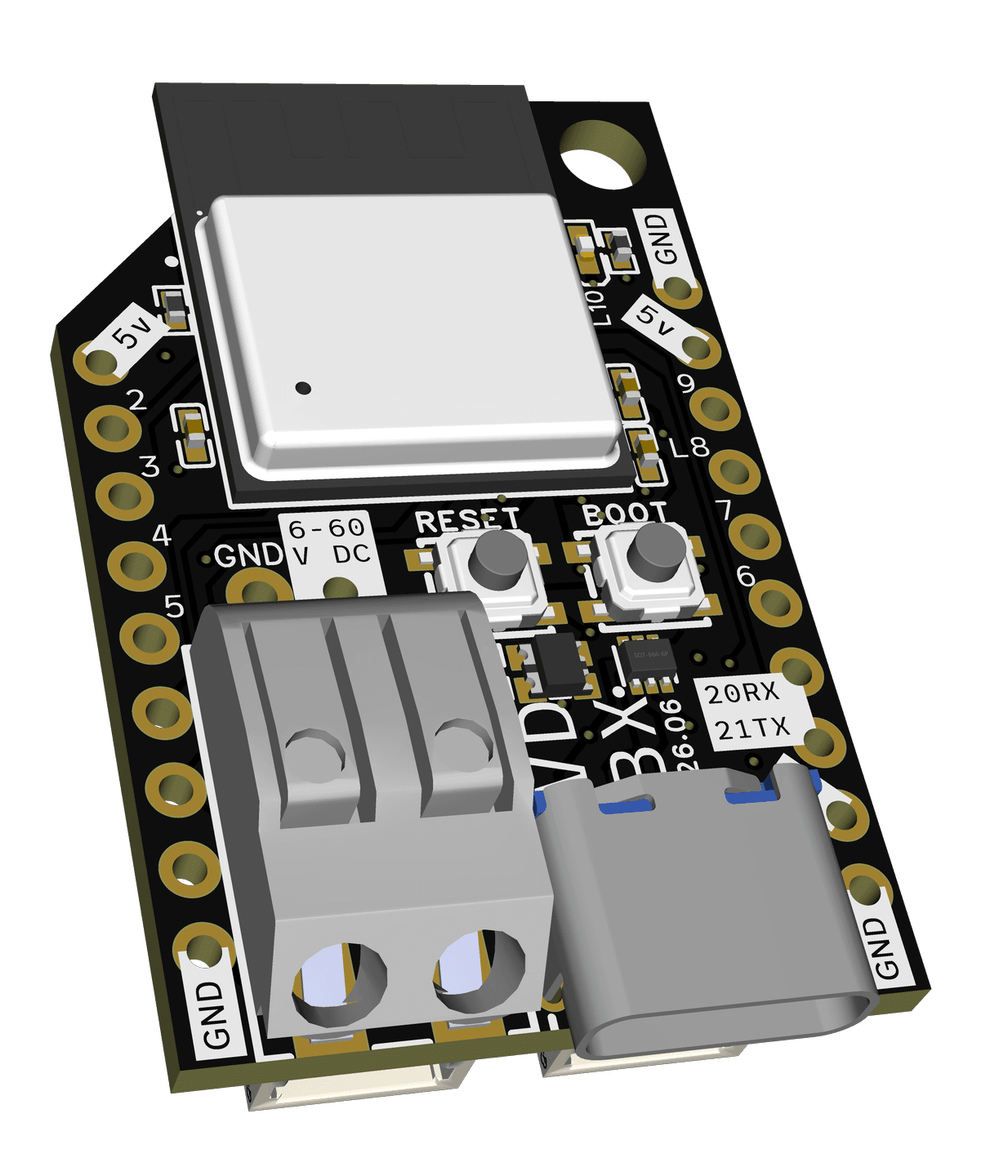
Section titled “Summary”The first development board for the FLIP Platform is an ESP32-C3 with a 60v tolerant buck converter meant for use with 12-48v battery systems. It is designed for use with ESPHome and Home Assistant, but can be flashed with other popular firmwares such as TASMOTA and WLED.
Now with official WAGO spring connector
Specs & Features
Section titled “Specs & Features”- On-board 5v/2A buck-converter tolerant up to 60v DC input
- V1.1+ - Full 60V input tolerance with transient suppression
- v0.x.x - v1.0.x - 60v absolute max, do not live connect over 50v
- Connect to battery when it is below 50v
- Install TVS in parallel with input capacitor
- Use a low value resistor to pre-charge circuit (pro move)
- Low-profile press-in wire connector for DC input
- 24-16AWG Solid
- 22-18AWG Stranded - Ferrules are suggested
- 2x2P 2.54mm pass-through power header for stacking
- Push release spring mechanism
- ESP32-C3 designed for ESPHome and Home Assistant.
- USB-C input for alt power and programming
- Reverse current protection from DC input via diode
- No data connection while powered by DC
- Reverse current protection from DC input via diode
- LEDs on-board
- WS2812B RGB -
GPIO8- Digital output available on header as
L8to drive short runs
- Digital output available on header as
- Red Status LED -
GPIO10
- WS2812B RGB -
- UART and I2C on Qwiic/Stemma QT compatible headers (SH 1.0-4P)
- I2C:
SCL0/SDA1 - UART:
RX20/TX21
- I2C:
- Boot Button
GPIO9 - Reset Button
ENABLE
The ESP32-C3 is considered a market replacement for the ESP8266 while bringing some features from the ESP32. It’s a RISC-V platform with Wifi & Bluetooth plus support for SPI Ethernet PHYs like W5500.
Pinout
Section titled “Pinout”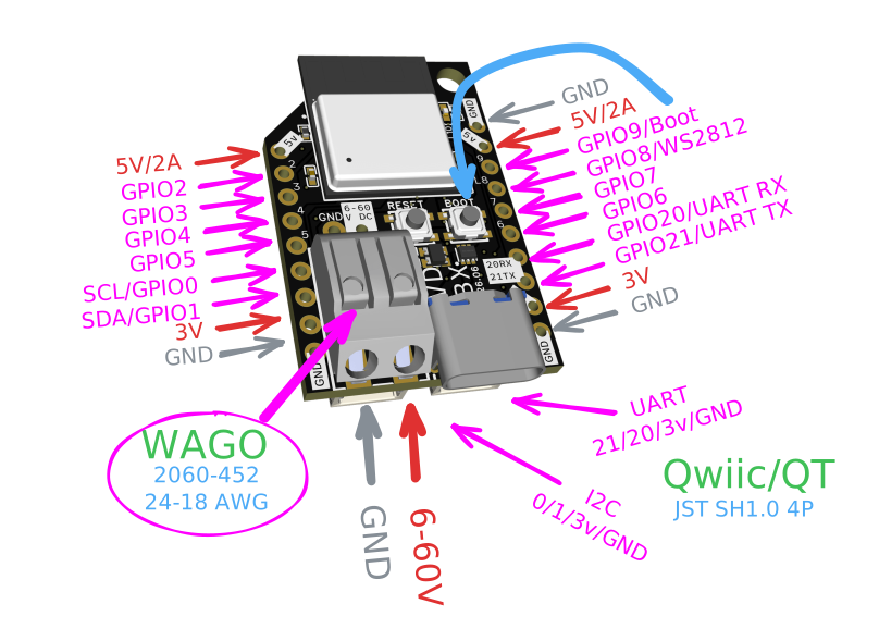
| Pin Label | GPIO | Notes |
|---|---|---|
| 5v | 5V/2A from buck converter | |
| 3v3 | 3.3V/1A from linear regulator | |
| SDA1 | 1 | GPIO1 - Used as SDA on StemmaQT/Qwiic Connector and FLIP header compatible daughterboards |
| SCL0 | 0 | GPIO0 - Used as SCL on StemmaQT/Qwiic Connector and FLIP header compatible daughterboards |
| RX20 | 20 | Hardware UART RX - Reassignable |
| TX21 | 21 | Hardware UART TX - Reassignable |
| LED10 | 10 | Not connected to header pin |
| LED8 | 8* | *Connected to header via DOUT of onboard WS2812 for level shifting |
| 9/BOOT | 9 | Hold button on boot to force bootloader mode - available as GPIO or on-board button in software |
| RESET | EN | Pulls EN pin low while pressed |
| 2 - 7 | 2-7 | GPIO Pins, check ESP32-C3-MINI-1 docs for special functions |
Home Assistant
Section titled “Home Assistant”BLE Improv
Section titled “BLE Improv”If you have the Bluetooth integration active in Home Assistant, you may be able to configure your FLIP_C3’s Wifi credentials directly. Hit the blue button below to check your integrations page.
Your FLIP_C3 will also create a Wifi access point as a backup.
network: flip-c3-xxxxpass: GenericPasswordIt should automatically present you a page to set your WiFi credentials, but if not, visit http://192.168.4.1/ in your browser.
Check your Home Assistant notifications or Integrations page to adopt your FLIP_C3 as an ESPHome device.

ESPHome
Section titled “ESPHome”It may behoove you to adopt into ESPHome Builder add your additional configuration before adopting into Home Assistant. Until you adopt into ESPHome, you will only have access to the following entities:
- 1x RGB LED
- 1x Red Status LED
- BOOT Button on GPIO9
- Reboot Button
- Hours Counter* (some installs)
- FLIP_C3 Internal Temperature
If you change the friendly name or hostname in ESPHome, you may need to delete and re-adopt the device into Home Assistant for these changes to be seen.
USB Recover
Section titled “USB Recover”Use the Connect button on the top left corner of this site to re-flash your FLIP_C3 over USB directly in Chrome or Edge.
Troubleshooting
Section titled “Troubleshooting”You may need to hold the BOOT button as you connect the USB cable. Alternatively you can hold the BOOT button while you press and release the RESET button if the FLIP_C3 is already connected via USB-C. Hold the BOOT button for a couple seconds after the device is connected to your computer and then proceed with the installation above. Once complete, power cycle the FLIP-C3 with the RESET button or disconnecting and reconnecting the cable. You can also use this time to swap to a DC power source via the 2P spring connector.
Adopt In ESPHome
Section titled “Adopt In ESPHome”Once you’ve followed the steps to connect your FLIP_C3 to Wifi, you should see it in the ESPHome dashboard available to be adopted. Adopting into ESPHome will generate a base YAML that references our YAML file on Github as an external package with the following lines:
packages: vdbxio.FLIP-C3: github://vdbxio/esphome-configs/flip-c3.yamlThis includes references to all the basics of the hardware and more. This includes the onboard WS2812, the red status LED, the Boot Button on GPIO9 and I2C is defined at id: bus_a
You can add ESPHome YAML to the end of this to get started quickly.
YAML Reference
Section titled “YAML Reference”The following are snippets to properly interact with FLIP_C3 hardware in ESPHome while direct reference to the YAML we ship is available on Github:
https://github.com/vdbxio/esphome-configs - Active repo as of 24.09
Board Definition
Section titled “Board Definition”If you like, you can easily start a blank ESPHome device based on the ESP32-C3 using esp32-c3-devkitm-1 board type. This is default in ESPHome for C3 based boards and we use chip level pin numbers on our silkscreen.
esphome:  name: bare-minimum  friendly_name: Bare Minimum
esp32:  board: esp32-c3-devkitm-1  framework:    type: arduino
Boot Button
Section titled “Boot Button”The BOOT button is available in software on GPIO9 after boot. If held during boot, FLIP_C3 will be put into bootloader/flash mode.
binary_sensor: - platform: gpio name: Boot Button pin: number: 9 inverted: True mode: input: True pullup: TrueWS2812
Section titled “WS2812”light: - platform: esp32_rmt_led_strip id: onboard_rgb rgb_order: GRB chipset: ws2812 pin: 8 restore_mode: RESTORE_AND_OFF num_leds: 1 name: "RGB LED"Status LED
Section titled “Status LED”light: - platform: status_led name: "Status LED" id: status_led pin: 10Get started with WLED
Section titled “Get started with WLED”WLED is designed for running addressable LEDs on ESP32 based devices and the FLIP_C3 is a great board for running it.
Use the installer at install.wled.me ->
Under LED Settings:
Set GPIO8 noted as L8 on the FLIP_C3 to use the onboard WS2812 as a level shifter. Increase your LED count by 1 to include this pixel. If you are close enough to your first pixel, you may be able to get a stable output from any other pin. Using anything but WS281x pixels on L8 may cause unexpected results.
Set GPIO9 as the button if you want to use the BOOT button on the face of the FLIP_C3
In the main interface
Use segments to separate onboard WS2812 from the rest of your strip.
Notes:
If using 5v LEDs with the on-board buck converter make sure not to exceed the 2A/10w current rating which is about 100 LEDs at full brightness.
The FLIP_C3 will get extremely hot over 1A. It should be able to maintain up to 2A in open air, but consider cooling when installing in an enclosure. Do not touch on-board components when in operation.
Changelog
Section titled “Changelog”Board dates are batch number referenced to a version number, though we haven’t yet done any duplicate production runs of a single version.
- 26.06 - v1.3 - Modernization
- Replace TE spring connector with WAGO
- Add GPIO2 pull-up for stability
- Add 3V/5V jumper selector for Qwiic connectors
- 3V Default - considering 5v in future.
- 24.07 - v1.1 - full input transient suppresion
- Add TVS diode to input -
- Move LED10 further from keepout zone - it has the room
- Tweak inductor position lower
- 23.12 - v1.0.1 - Prep for early 2024 production
- Moved C14 closer to EN pin
- Research potential replacements for L1 based on price and availability
- 23.08 - v0.9.4 -
- Original DC spring connector only grabbed the tip of standard length ferrules making solid core wire the only real option
- second option was too small & original is now discontinued - 0.9.5 is on the way with third option
- Instead of presenting GPIO8 directly to the pin header which is used for the onboard WS2812b, we now route the D-OUT from the on-board WS2182b to an “L8” pin so it be used as a level shifter for short runs.
- Original DC spring connector only grabbed the tip of standard length ferrules making solid core wire the only real option
- 23.04 - v0.9.1 - Switching Buck Regulator
- LMR16020 - tested to work from 5 to 58v with only FLIP-C3 as load
- higher voltages seeing upwards of 0.6v wobble on output
- output is up to 0.7v higher at 58v input vs 5v input
- Missed output ground on test board and poor placement of VREF
- LMR16020 - tested to work from 5 to 58v with only FLIP-C3 as load
- 23.04 - 0.9.0- LDO circuitry is not going to work, back to the drawing board.
- Design and order tester for switching buck
- Remove LDO circuitry from FLIP-C3 and
reconsider footprint size.
BOM Alternates
Section titled “BOM Alternates”The retail version of the FLIP_C3 is currently manufactured by JLCPCB using their parts library. While it is said that JLCPCB uses their sister company LCSC for parts, the two companies usually have different stock. This is a living document of potential alternates for major parts including those used in production or considered for production. This document can be used in case of stock declines or discontinuation of parts. Basic passives like resistors and capacitors may not be included as this is intended for major functional parts and those parts can be easily replaced with a simple search when using the BOM directly from the EasyEDA files.
I2C & UART Connectors
Section titled “I2C & UART Connectors”For Qwiic and Stemma QT compatibility we use JST-SH1.0 connectors based on SM04B-SRSS-TB(LF)(SN) via reference document from Sparkfun
A second connector is used to connect to the RX/TX lines on GPIO 20/21 alongside GND & 3v3 in the same order as the I2C connections on GPIO 1/0 - See PINOUT
ESP32-C3
Section titled “ESP32-C3”There are two variants of the ESP32-C3-MINI-1 module. The H4 variant has a higher temp tolerance than the base model N4. We’ve focused on using the H4 variant, but supply chain issues could lead to us using the N4 model in some production runs.