USB-C Modkit for Apple TV 4K
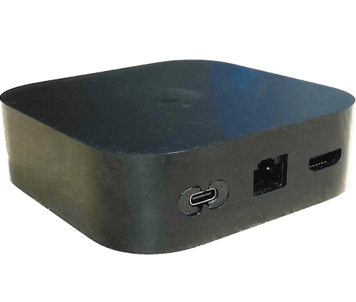
Power your Apple TV with USB-C
FilesApple TV USB-C Mod v21.f3dShroud-ATV2022Modkit.stlSpacer-ATV2022Modkit.stl
Works with A2843 · A2737 · Apple TV 4K (2022)
Included in kit:
Section titled “Included in kit:”- 1x Modkit PCB with Linear Regulator
- 3x Guitar picks to open case
- T6 Allen key to remove power supply & power connector
- Connector shroud -
3D Printed - Insulating spacer -
3D Printed - 2x M2.5x8mm Screws with T6 head
- Quick Start Card
Summary
Section titled “Summary”The AppleTV seems to have always been the only TV streaming box that isn’t powered by a USB cable. This mod kit changes that, keeping a clean unmodified look. Grab any USB-C cable and any charger that can provide a stable 5V/2A for best results
Installation
Section titled “Installation”Opening the Apple TV
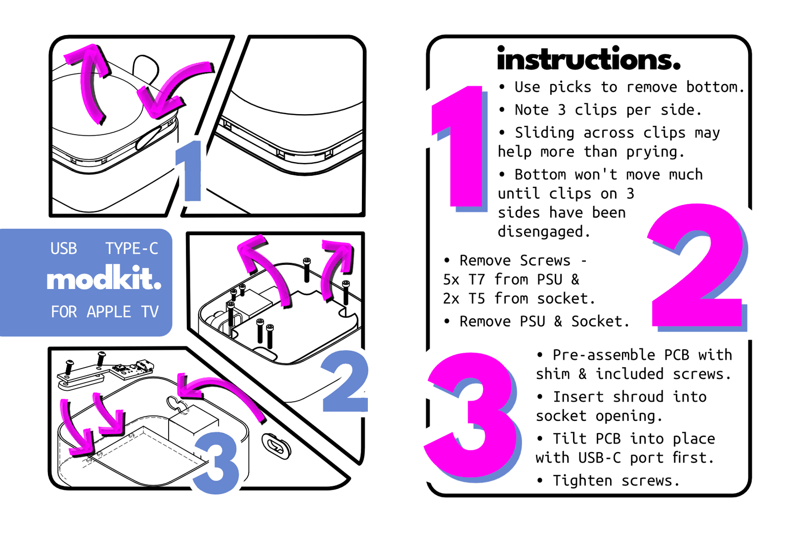
Section titled “Opening the Apple TV”Use the included guitar picks to open the AppleTV by inserting them into the seam near the bottom edge to release some clips. This can be tricky if you aren’t used to it as it is nearly right on the corner and very well hidden.
- There is a slight lip inward and then it goes straight up.
- There are three clips on each edge with the side clips about 5mm in from the corner radius
- The goal is all three clips on 3 sides
- No need to go around the corners.
Remove PSU and Power Connector
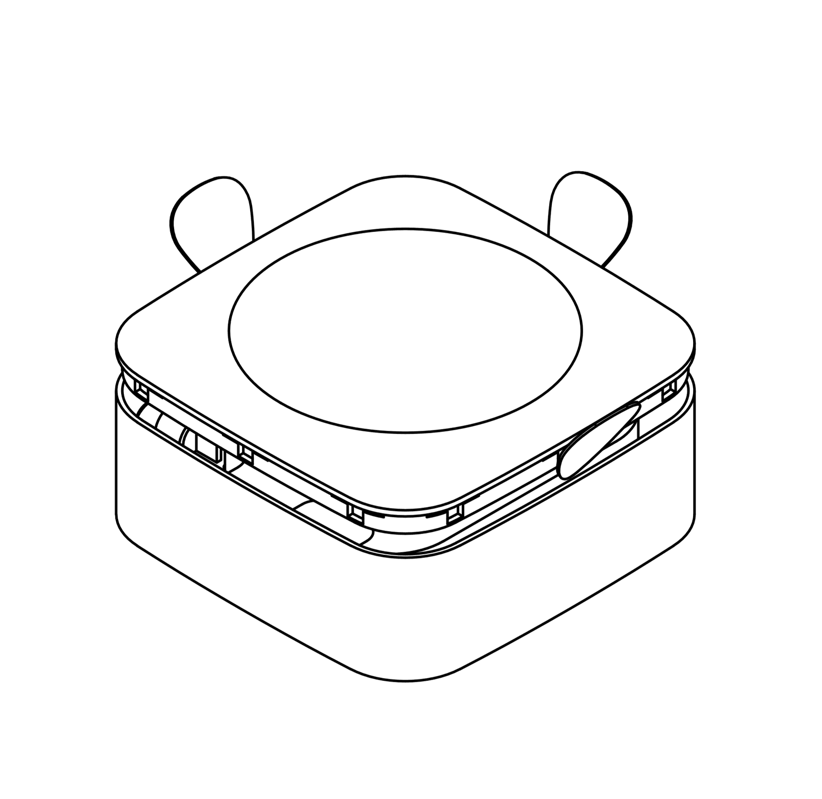
Section titled “Remove PSU and Power Connector”There are 5 T7 screws around the PSU and 2 T5 in the power connector. The included T6 allen key has been tested to fit both, but may be a tight fit in the T5 screws. Remove these screws and discard the PSU and connector. You may choose to keep these items in a safe place in case you choose to revert this mod.
Install the Modkit
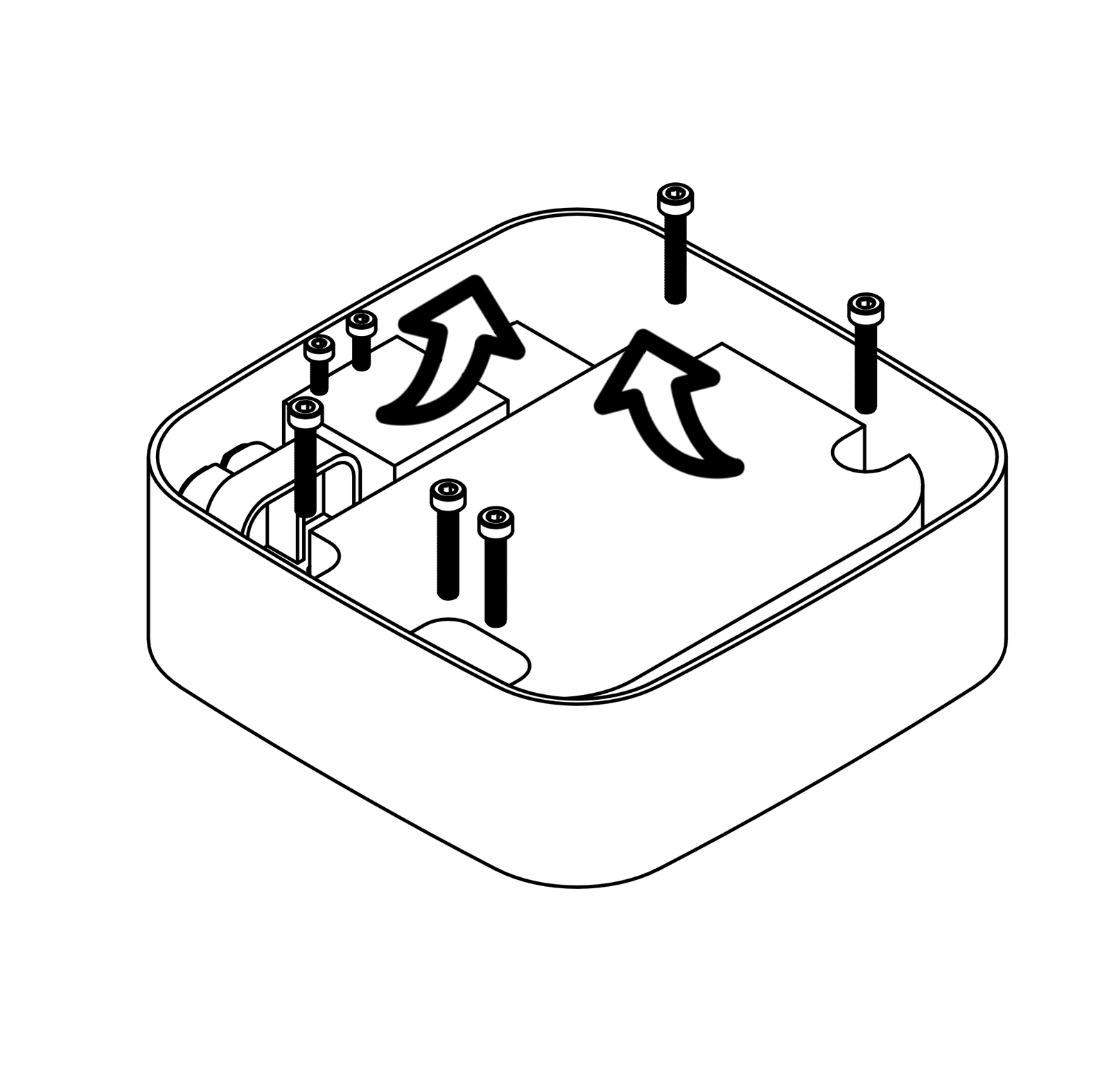
Section titled “Install the Modkit”1) In the small bag remove the plastic shroud and place it in the opening where the original power connector was. It should snap in or at least stay in place enough for the next step which will lock it in.
2) Pre-assemble the remaining items of the kit as shown in the image below. The holes in the insulator/spacer are slightly smaller than the included M2.5x8mm screws so the whole assembly can be placed together without fumbling. The screws should go through the text side of the circuit board and into the insulators.
3) Align the USB-C port in the opening of the shroud from Step 1 and then lower the opposite side towards the screw holes left over from removing the PSU. As shown in the image below, you want to use the two inner screw holes and not the very far one.
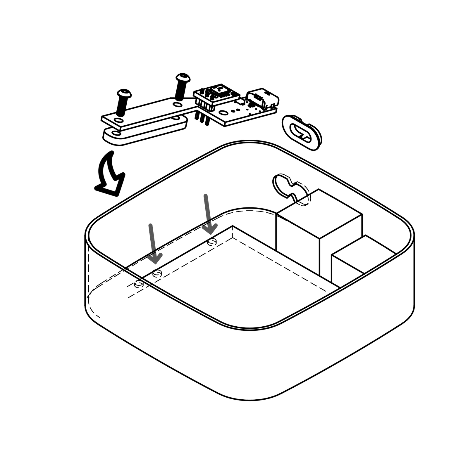
Change Log
Section titled “Change Log”There is no official versioning aside from board production dates based on YY.MM standard
- 26.02
- First run with Elecrow as contract manufacturer
- QC testing in place to maintain 4.3v +/- 0.1v
- Updated professional packaging
- New getting started trading card
- New screw supplier
- First run with Elecrow as contract manufacturer
- 24.06
- Combined external LDO circuit into main board
- Extended ground plane to get final smoothing cap closer to output
- Add bottom GND plane and add stitching vias
- Remove unused secondary GND screw mount
- 23.12.11
- Diode removed from design
- Submitted second batch to use with LDO boards still in stock
- d23.05
- LDO add-on board works and will be used to adapt the first batch for retail production
- Re-design with LDO circuit on-board if first batch sells-out
- 23.04.10
- Tested with 5.1v direct from USB, would not boot. Recovered when given its average 4.7v ish.
- OE PSU was 4.3v, but Diode does about 4.7v and is not super stable based on current draw.
- LDO add-on board designed and ordered.
- v1.0 - First run in testing
- Works but some questionable behavior - unable to attribute to mod kit
- voltage is all over the place with diode used… test raw VUSB and optionally test an LDO
- would love to test max voltage, but that would require breaking my only Apple TV